I’ve built a few machines since my first, a 2D plotter, I plan on writing about all of them but I might as well start at the beginning.
The reason for building the 2D plotter was that I had just learnt about stepper motors and was desperate to use them for something, so I thought I’d start with a simple 2 dimension device.
A 2D plotter moves a pen along paper to draw a pattern fed by the computer. There aren’t many uses for a machine like this but it’s pretty cool to watch.
NOTE: I built this machine in 2010 so I’m writing about this about 5 years after the event so some details might be wrong.
The components
The plotter was made from
- 3 printers
- 1 portable CD player
- 2 unipolar stepper motors
- Some electronics
- An old computer PSU
- Polymorph plastic
- An old bit of MDF
- Some cheap servos
I started on the 4th of Feb 2010 by purchasing an HP Photosmart 7260 inkjet printer, and on the 6th ordering another one I don’t know the model of. I know the exact dates because I still have the emails from eBay.
After I began building the machine I realised I would actually need another secondary X axis for stability so I bought another printer at a bootfaire for £1. The main parts I needed from the printers were the belts, the frames, and the pulleys. I think I spent about £15 in total on the printers.
I also bought a couple of unipolar stepper motors and a bag of Polymorph plastic also from eBay for probably £20 in total. I would also need an old portable CD player, I found that in a cupboard.
Assembly
I assembled the different parts over quite a long period of time. I had no job at the time and no other sources of income so it was slow getting everything I needed.
The frame bits
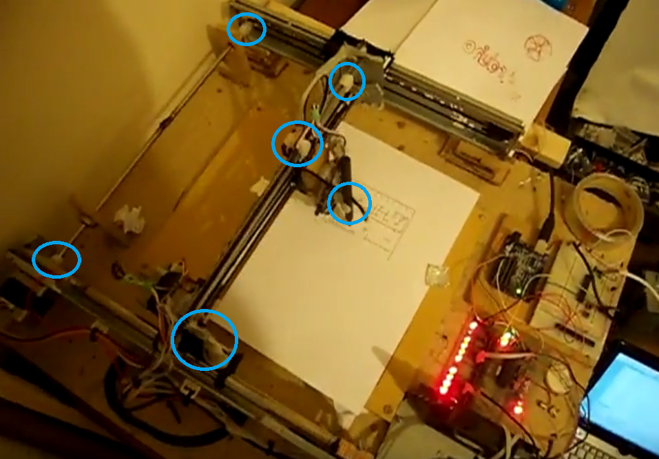
I tore the printers apart and extracted the parts I needed. After that I fitted them onto a piece of MDF with screws, polymorph, and superglue.
Before I had access to 3d printing I would use Polymorph plastic to create any custom parts required. Moulding a polymorph part was a difficult and annoying process.
You first have to heat the plastic to about 70 degrees celcius in a microwave so that it becomes the consistency of plasticine. This is quite a tricky process to get right, too hot and it will stick to your skin and cause horrific burns. Too cold and you won’t be able to get it in to position before it hardens.
Then you have to hold the parts in position while the plastic cools and hardens, this is super annoying as it has quite a high thermal capacity and can take minutes to cool. The last problem is that, like most things, it shrinks when it cools, which means that you have to consider that while shaping it.

The electronic bits
Once I got the basic shape sorted, and all the rod joiners and mounts in place, I had to start on the electronics to control the motors.
I had almost no money so I couldn’t get a standard CNC stepper motor control board so I had to build one.
I used ULN2003A transistor arrays to control the motor coils and Arduino running on an ATMEGA168.
This setup was super dodgy and prone to problems most of all because the original design didn’t have flyback diodes on the coils so the chips were consistently destroyed. I only later realised that the ULN2003A had build in flyback diodes that I just had to connect properly.
The pen mount
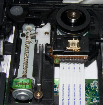
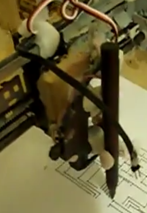
Now that I had the rest of the hardware clumsily assembled, I had to move on to making the pen mover thing. I wasn’t really sure how I was going to do this until I started thinking about devices that had parts that moved up and down in a linear fashion. Then I remembered how CD drive lasers move up and down to read the disc. I found an old portable CD player in a cupboard and salvaged the laser mount bit.

(image from wikipedia)
I don’t have any pictures of the one I had at the time but it was similar to the one above, only it was a normal DC motor and much smaller as it was portable.
So to control the position of this makeshift linear actuator I took the electronics from a 9g micro servo and connected it to the motor along with a linear potentiometer for feedback.

The software part
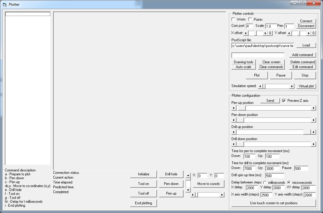
So this was a time before open source CNC software had become ubiquitous, let alone even if it was, I was on some mad spree to prove I could program anything. So I started writing the control software using Arduino for the firmware and Visual Basic 6 for the control. Visual Basic 6 is obviously a terrible choice of programming language, just to make that clear, but I was pretty new to software development and VB6 was all I knew.
Preparing the data was the first stage for making this thing work. I had to get an SVG design into coordinates that could be fed into the plotter. I found a series of tools that I could use to create a HPGL file which contained exactly what I needed. HPGL is a format created by HP spcifically for plotters.
The next problem was that with this data being fed into the ATMEGA 168 through the slow TTL serial connection it would work brilliantly on straight line drawings but slow down on curves, because the points were too dense.
I tried buffering the data inside the microcontroller using a circular buffer, which helped but the problem with this is that you get a nice fast curve for about 1-2cm of travel then the buffer is exhausted and your bottleneck is the serial connection again.
I never worked around this problem but realistically I should have reduced the level of detail on the input data. Or maybe got a chip with more memory.

I had to install Visual Basic 6 and search old hard drives just to get this screen shot. Quite funny to look at the old code though. I couldn’t find any hpgl files to load into it but basically it would render a preview in the middle and list the coordinates on the left.
The end
In the end it worked fairly well, I got it to draw some pictures. See below.
Some other vids here and here.
The knowledge from this 2D plotter turned out to be quite handy when I started on my first version of my 3D printer.