I had just seen the first news article on 3D printers, and I knew immediately I had to build one. Up until hobbyist 3D Printers existed you were stuck using wood, glue, polymorph and whatever else you could cobble together to build things. So when I heard about RepRap I saw it as the way that I could build whatever I wanted. I could finally build things in a precise way, rather than cobbling crap together into a slightly more organised pile of crap.
After building my 2D plotter I was confident that I could do it, the problem is that I was still jobless and had almost no money for parts. This was July 2011, and from what I can remember 3D printing had not become wildly popular, so things like smooth rods, linear bearings, belts etc hadn’t become as abundant and cheap. So I had to build this thing with as few bought parts as possible. The lucky part was that I had a garage full of tools and bits that I could scrounge from.
Designing the printer
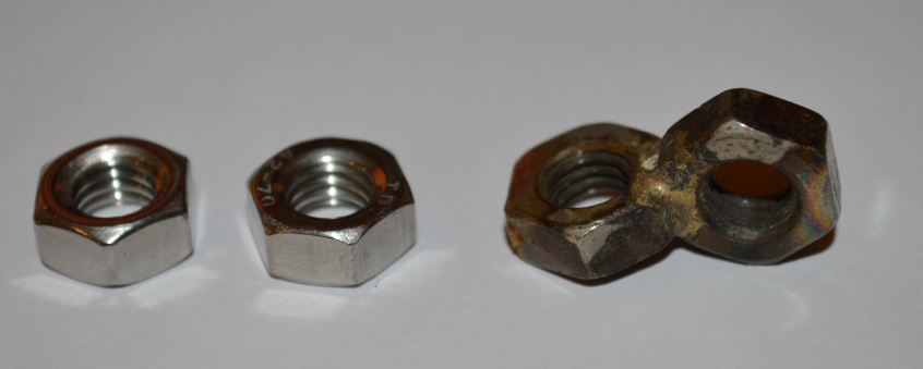
The design for the mark 1 3D printer was based on an idea of scaffolding. While I had limited components what I did have abundant supplies of were studding and 13mm nuts. The problem is that they don’t really make an 90 degree angled nut so I based my design around the idea of brazing 2 nuts together at right angles and using those to build the printer.
I had no idea about 3D modelling so I searched for the for a program and found a discontinued one called Caligari Truespace. I didn’t really know how to use the software but I figured out enough to design a rudimentary model. Annoyingly after searching through old hard disks for ages I just couldn’t find the original models for this printer, to be honest they were pretty terrible anyway.
Assembly
Modelling the printer ahead of the assembly was quite a time saver when it came to the ordering of the brazed nuts on the studding. I worked out that I’d need something like 40 brazed nuts to build it. As each one took like 2 minutes to wind on to the studding I didn’t want to put one in the wrong order and have to unscrew half of them just to fit the missing nut on.
The right angle nuts
So I bought some brazing rods on ebay and went to assembled some of these brazed nuts. This is when I encountered the first problem - the blow torch in garage just wasn’t hot enough to braze. I had to buy a swirl flame blow torch. This was a massive set back in terms of cost but at the time I couldn’t see a way around it.
The next problem came when I actually managed to braze the nuts together, I realised it’s actually really hard to line up 2 nuts at perfect right angles while heating them to 500 degrees. I powered through this and got better but still only had about a 50% success rate. The failures were mostly due to: the wrong angle, the thread being ruined by the flux, and the nuts deforming from the clamps.
Naturally I needed more than brazed nuts to assemble this printer, for everything else to do with the frame I used mostly polymorph.
Frustratingly I didn’t take many pictures of this 3D printer, I did however manage to find some pictures I took while making some measurements, and when I started tearing the printer apart at a later date.
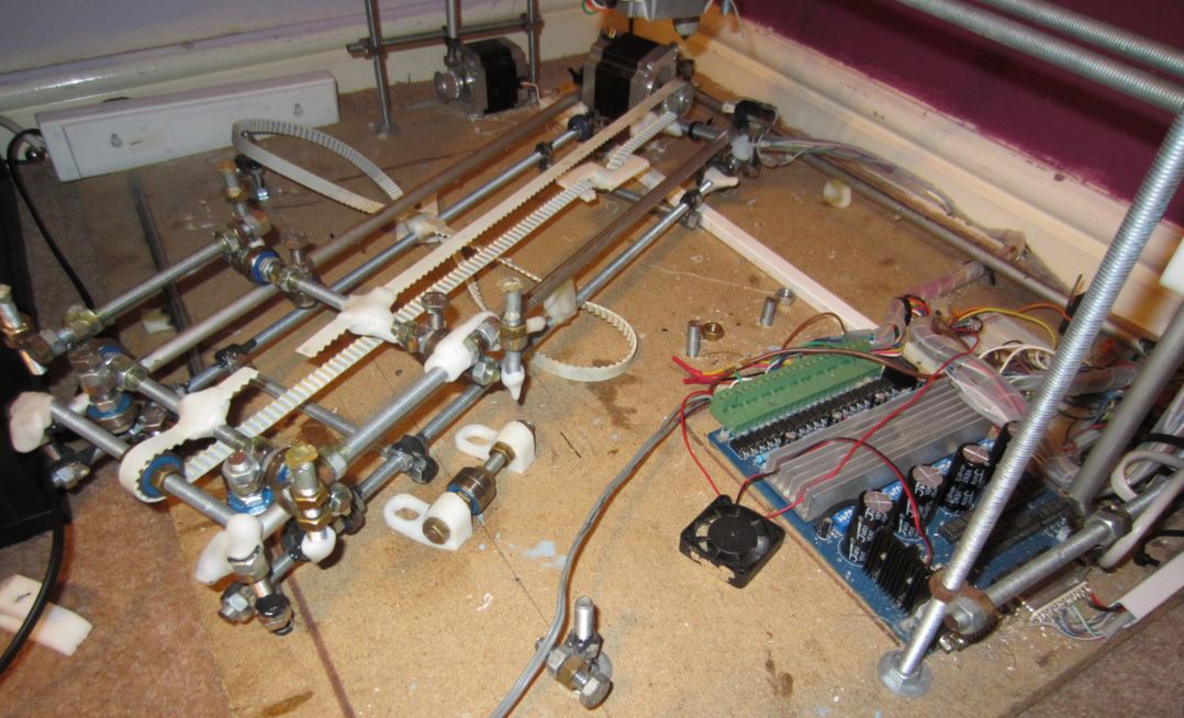
You can see how the right angled nuts come together to form a sort of scaffolding.
The smooth rods
The other essential parts for CNC machines are the smooth rods. Smooth rods back then were really expensive, so I needed some sort of alternative. I went down to Wickes and found aluminum tubes were fairly cheap, the problem obviously is that aluminium tubes are not straight.
I found that by rolling the rods on a flat surface it was fairly easy to identify where they were deformed and bend them mostly back into shape.
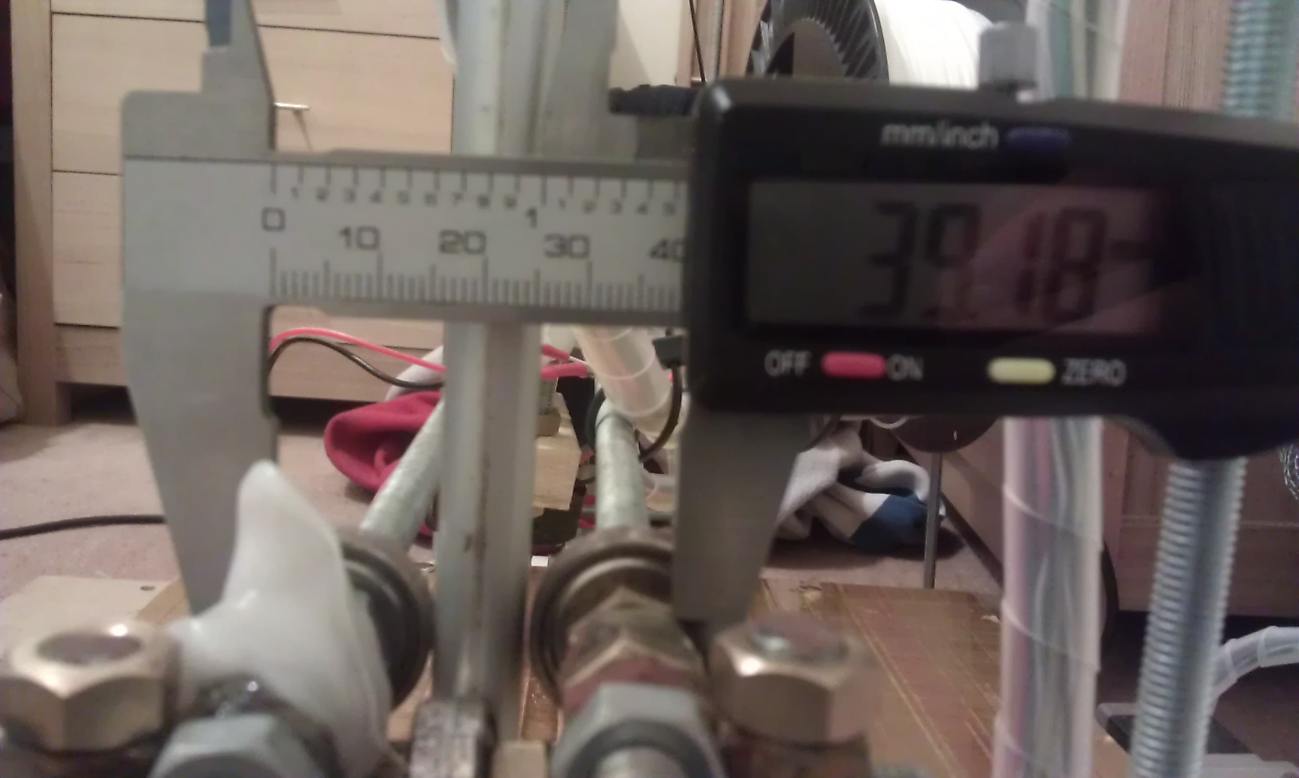
You can see the aluminium rod in the above picture in the center between the bearings.
On normal 3d printers you’d use linear bearings with the smooth rods to guide the axes. Now I’m not sure why I didn’t use them on this one, it was either that I didn’t know about them, or they were prohibitively expensive at the time. As you can see in the picture, I used a sort of roller coaster wheel design for the bearings that support the Z axis.
The extruder
The main thing that differentiates a 3D printer from other CNC machines is the extruder. I needed to cobble together some sort of extruder as cheaply as possible from bits a bobs. There are a couple of special considerations that need to be made around the extruder.
- The extruder head needs to operate for hours continuously at 200°C.
- The filament needs to be fed in with an incredibly large amount of force.
- The hot end needs to be able to handle a large hydraulic pressure without deforming or leaking.
- The actual nozzle needs to be ideally < .3mm
- The filament input tube needs to be tight on the filament or the melted plastic will leak up the input tube rather than being forced out the nozzle.
I went through alot of different ideas, and took inspiration from the existing hot end designs on the internet and eventually got to something that mostly worked.
The feeder
The feeder pushes the filament into the hot end forcing it out a smaller diameter nozzle. I was pretty sure I could assemble most of the parts from the beginning, the only parts I definitely couldn’t make myself were the gears that drive the filament into the hot end. I bought 2 cogs designed for use in remote control cars which seemed like they’d be able to hold up to the forces, and provide an adequate gear ratio for the steppers motors.
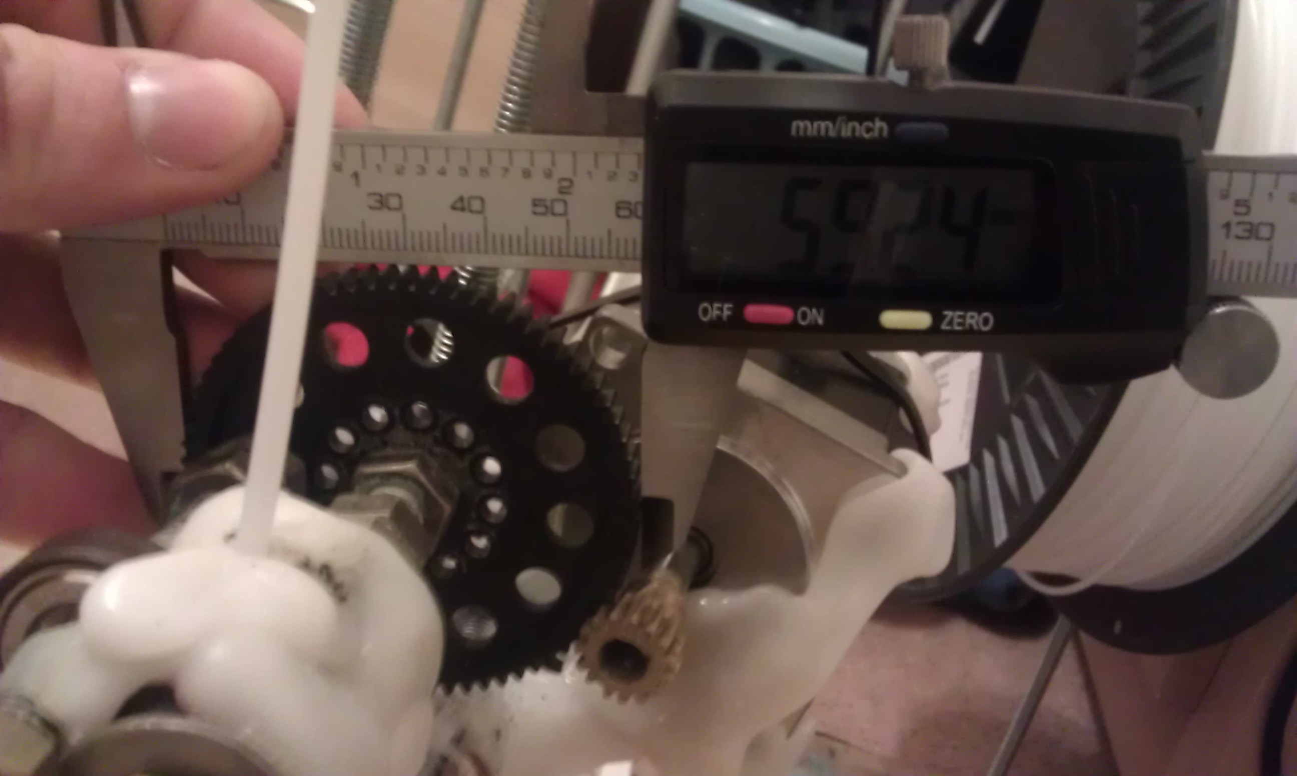
You can see in the image that I’ve used large quantities of polymorph to hold the parts of the extruder together.
The filament is fed by pressing it against a hobbed bolt and rotating the bolt, this is a pretty standard design for 3d printers. See here for the the process I basically used to make the hobbed bolt.
The hot end
The nozzle was probably the hardest part to get working due to amount of precision required and the amount of stress it would be under. Nowadays you can buy a fully assembled hot end for about £30, back then they were no where near as cheap and I also still had no money.
I started by rummaging through our garage for something that might have the right size shape and eventually found a 5mm mig welding tip. While the nozzle diameter was a little bit bigger than I wanted, it was the closest I was going to get.
Before I could get to brazing the welding tip, I had to drill a 3mm hole through the studding. Normally this would be a fairly straight forward process with a drill press, unfortunately I didn’t have one. I clamped the studding in a vice and somehow managed to hold the drill fairly straight leaving me with a fairly straight hole right down the center.
After brazing the tip to the studding I could then screw it into a piece of PTFE which would act as the heat shield.
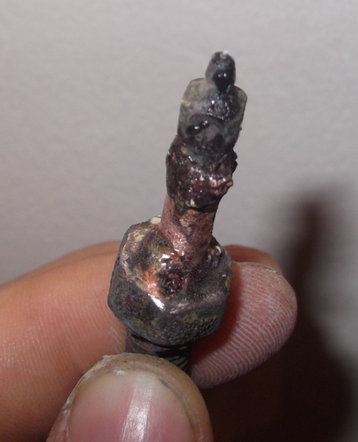
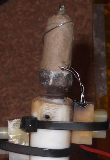
The next part was to actually make the hot end hot. I wrapped a thin layer of fire cement around the nozzle, about 2mm thick, then wound about 25cm of nichrome wire around it. I think this worked out to be about 100watts at 12v. I then wrapped the nozzle in another layer of fire cement to keep the coil in place and to provide some extra thermal stability.
The hot bed
A hot bed is a heated platform that the plastic is extruded onto. Usually this is made from a PCB with the coils etched onto it. Again, these weren’t so abundantly available at the time so I had to come up with something else.
What I had available was a small sheet of aluminium which wasn’t ideal but worked ok-ish. I then needed some way to heat the platform evenly. I considered using nichrome but I couldn’t think of a way of mounting it nicely to the aluminium.
So I went to Argos and picked up 4 pairs of the cheapest hair straighteners I could find, dismantled them, and extracted the heating elements.
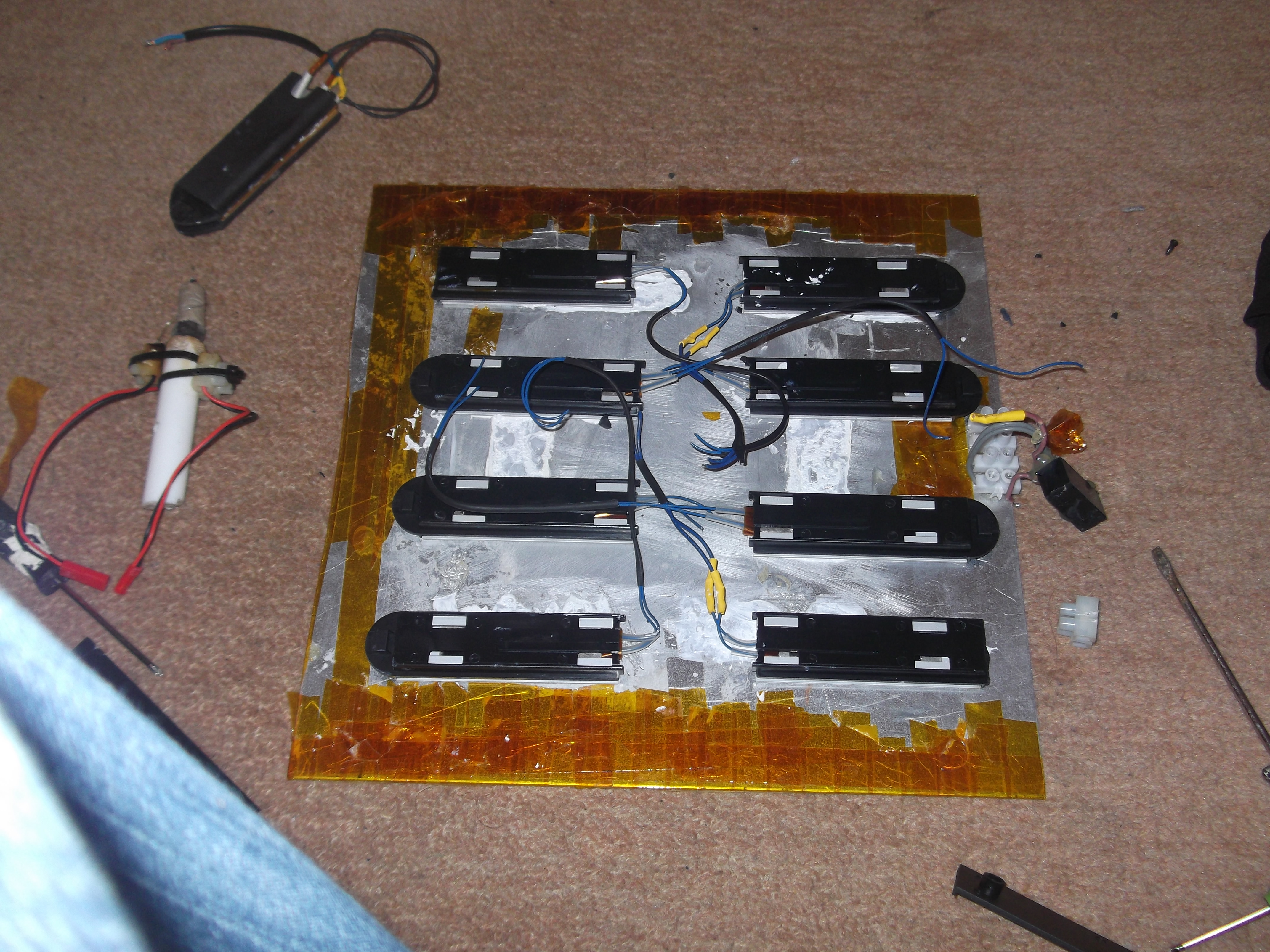
I used thermal compound to help conduct the heat between the straighteners and the aluminium. There is a relay in there for the electronics to control the heaters, which run off the mains. After I took this picture I then secured them with silicone. Looking back, this looks super dangerous.
The electronics
After the amount of annoyance I went through assembling the electronics for my 2D plotter, I opted for a pre built 4 motor CNC stepper control board. Even though this board was expensive at £50, it worked brilliantly and I still have it to this day.
The thing about these CNC control boards is that they are designed to be controlled by a parallel port. So the first thing I had to do was work out what pins did what, then fashion a cable I could attach to my Arduino. This would have been made easier if there was a manual or anything with this board, or if the ones online didn’t contradict each other.
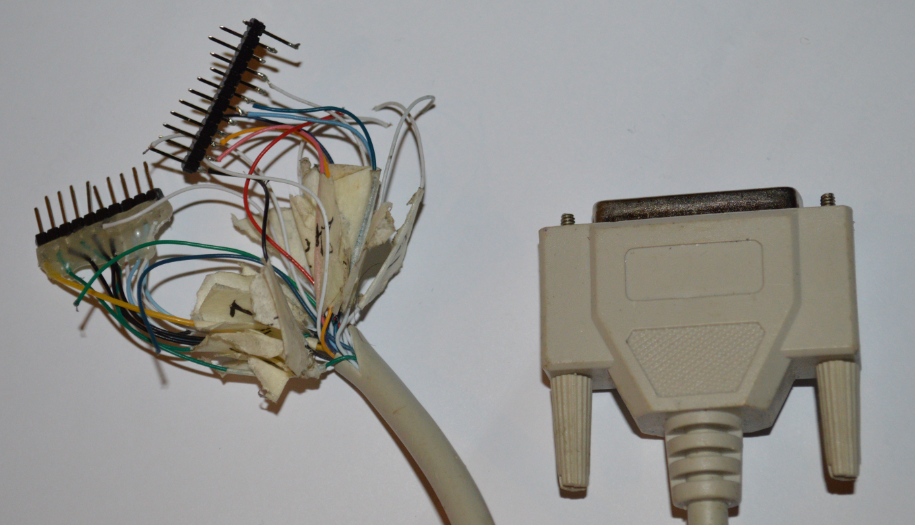
Using a pre built board meant I only really had to wire in a few mosfets for the high current switching on the heaters, and a few thermistors to read temps.
Software
I used the standard reprap software and Skeinforge on this printer. I spent so many hours fiddling with the settings in Skeinforge to get it working. When I switched to Slic3r on my mark 2 3D printer it was like turning on a light switch compared to operating a nuclear reactor.
The end
Once everything was together I started printing things. It worked ok, it wasn’t amazing but it worked. It definitely wasn’t reliable though. I had constant problems with it and eventually completely rebuilt it, but it was fun to make I guess.
Here is a video of a slightly larger model being printed.