I wanted to build some small devices that I could take around with me, the problem was that I could make great cases for these things but I couldn’t actually make PCBs for them. A standard way of doing this is to print the PCB design onto transfer paper and then iron it onto the PCB and etch it in acid. This would have worked but I didn’t like the idea of having to use acid every time I wanted to prototype a PCB, and I also didn’t have a laser printer.
I found a method people had been using online that involved using a milling machine to carve away the unwanted copper leaving the traces you want. This method appealed to me due to the lack of acids and the general lack of consumables of any kind besides the copper clad board. Looking at the prices of these machines I realised that there was no way I could afford to buy one, so I would just have to build one.
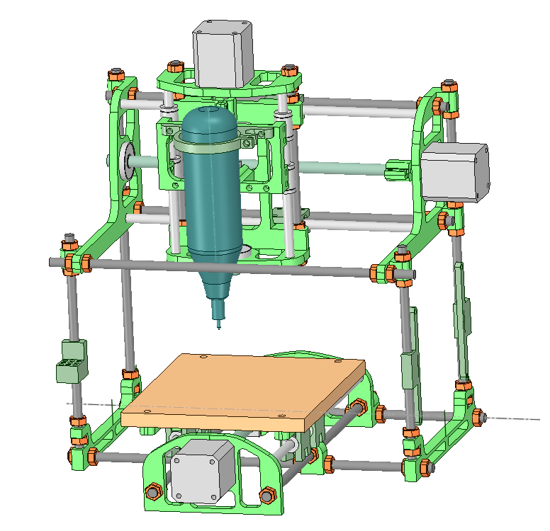
The design
From my previous projects I’d realised that any part of the finished product that was not considered at the design stage would almost always be a pain to fit in later. So I spent a good amount of time getting the design complete on this before I began manufacturing. This was especially important considering how long 3D printers take to actually make stuff, any mistake would cost hours of machine time.
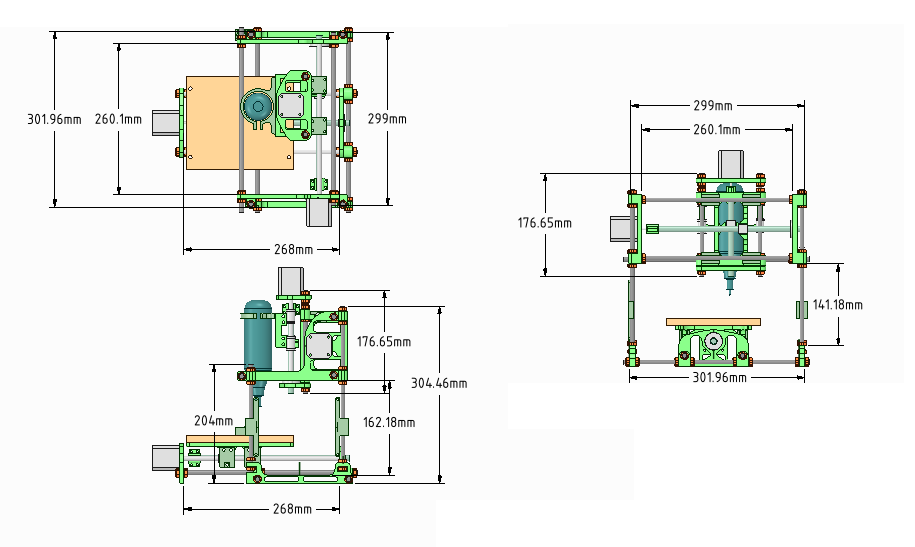
For this machine I decided to go with a X + YZ configuration, with the Z axis being mounted inside the Y carriage. This choice was made mainly because of the cost of trapezoidal lead screws, which I still maintain is outrageous.

This machine had a fairly small build area, probably about the size of an A5 piece of paper. I wasn’t too bothered by this as the sort of things I wanted to manufacture were going to be very small anyway.

Components
The components from this design were pretty standard hobbyist CNC supplies. This sort of machine was about 10 times simpler to design and produce compared to a 3D printer. You didn’t have to worry about temperature or consumables, and controlling it essentially boiled down to 3 decimal positions and a boolean input for the mill.
The lead screws
For this machine speed was not a problem, I didn’t care how slow it worked my highest priority was absolute repeatable accuracy and precision. I wanted to be able to carve traces .1mm thick if necessary. For this I went with 2D trapezoidal lead screws, which means that for every 1 turn of the lead screw you get 2 millimeters of linear movement. This combined with microstepping on the motors meant that I could theoretically get a precision of 0.000312 millimeters. Of course the actual machine would be nowhere near that accurate but it meant that from the beginning there would be no inherent imprecision.
The rods
I considered using 10mm round bar for this printer but then I looked back at an old 8mm bar I’d used and though that it would be rigid enough to support the weight without bending. My concern was that at the center of the axis the weight of the Dremel and Y carriage would cause the Y rods to sag. The threaded rods that held the rest of the frame together were standard 8mm studding.
The rotary tool
The rotary tool was one of the biggest concerns for me as I knew they were fairly pricey for decent ones. When advertising their products, rotational accuracy was not something that they listed or people reviewed, so it was hard to determine if I’d be able to do what I wanted. I ended up doing some tests on a super cheap one from my parent’s garage, purely holding it still and looking at the tip rotating at 18000rpm. At this speed any flaw in the tool was very obvious, and I could see immediately that it was not stable.
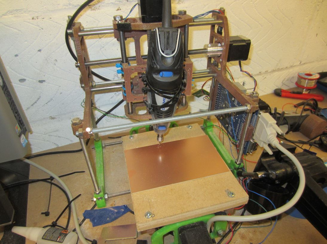
I ultimately decided to buy a Dremel Hobby 300 Series at just under £50, which had really good reviews. It worked flawlessly and gave incredible precision at maximum speed.
The electronics
I bought a 3 axis CNC stepper motor control board on ebay from china for something like £30 which also contained a relay which I could use to switch the dremel on and off. I didn’t need any other electronics because I just happened to have an old computer with a parallel port available.
Assembly
I started printing this machine piece by piece and assembling it as I went. The actual printing took quite a while due to the number of individual parts required and their volume. Actually assembling the printer wasn’t a problem and was quite uneventful, after getting the design complete this machine was essentially just assemble by numbers. I did have a few problems mounting the rotary tool to the Z carriage, but I resolved that with a inordinate amount of tie wraps.
The result
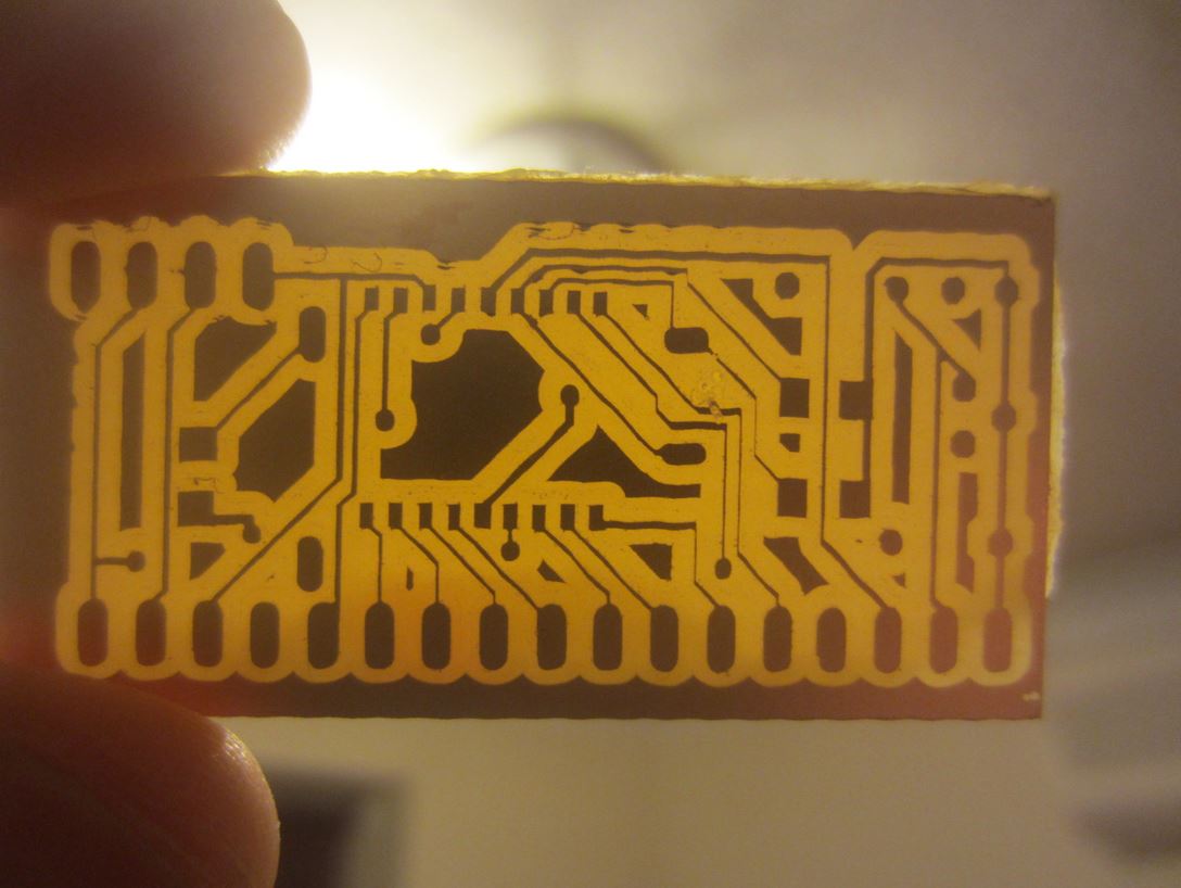
The machine worked as well as I hoped it would, and I didn’t really deviate from the initial design very much. I was able to carve traces thin enough for 0603 sized surface mount devices.

One of the final problems I had was a minute wobble on the Y axis which can be seen in the output below. This turned out to be caused by a slight angle on the shaft connector between the motor and the lead screw.

Here is a video of a PCB being cut, at this point I hadn’t calibrated the axes correctly so while this is the same PCB design as the image above, it’s scaled up by about 100%.
Note: This video is pretty loud