While building my quadcopter I had the chance to play around with brushless DC motors, and came to appreciate the immense power to weight ratios they had. I wanted to use a large motor in something and I had my 4th mobility scooter sitting motorless in the garden, so I thought I’d to attach one to that.
The components
The first stage in designing this machine was to find a suitable motor. After looking for a while I found an Overlander T4260 1300 watt 500kv motor for £70. I calculated at this kv rating, after hooking it into the mobility scooters existing gearing, would bring the speed up to something near 14-15mph.
The only other bought parts were the electronic speed controller, a Hobbyking 80A ESC designed for RC helicopters, and 2 11.1v 2AH LiPo batteries.
The design
This mobility scooter had an interesting connection from the motor to the slip diff. The rotating connector on the scooter was a small bar that acted as key to the motor shaft adaptor. I modelled this connector and the screw holes from measurements on the scooter’s gear casing.
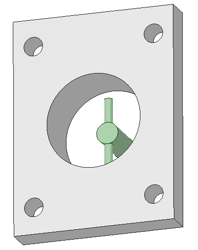
Unlike my other projects, I would be trying to fit parts to an existing frame so there was less up front design and more iteration. There were two major designs I went through for this scooter which were differentiated by the way that the motor was attached.
The first design
With the first design I did the most obvious thing which was to connect the motor’s shaft to an adaptor and then connect the adaptor to the gearbox. I used a collet type shaft adaptor on the motor with an 8mm nut to hold it tight. The flaw in this design was that the gearing caused the motor to rotate against the direction of the nut, which meant it was constantly trying to unscrew itself.
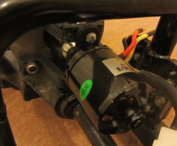
This would work for a while but inevitably the torque from the motor would force the nut undone.
The second design
This type of motor is called an outrunner because unlike regular DC motors the windings remain in a fixed position and are the stator. The case becomes the rotor and is attached to the shaft of the motor. This allows the motor to be rotated without brushes and allows high strength neodymium magnets to be used in extremely close proximity to the coils. This results in incredible power and efficiency. It also means that the heat generated by the coils can be more easily dissipated.
You can see the motor in action in this video
I realised that I didn’t actually need to use the motor’s shaft at all and it could essentially be ignored. So I designed a new mount that worked on the premise of flipping the motor over and bolting the case to the adaptor that interfaced with the gearbox.
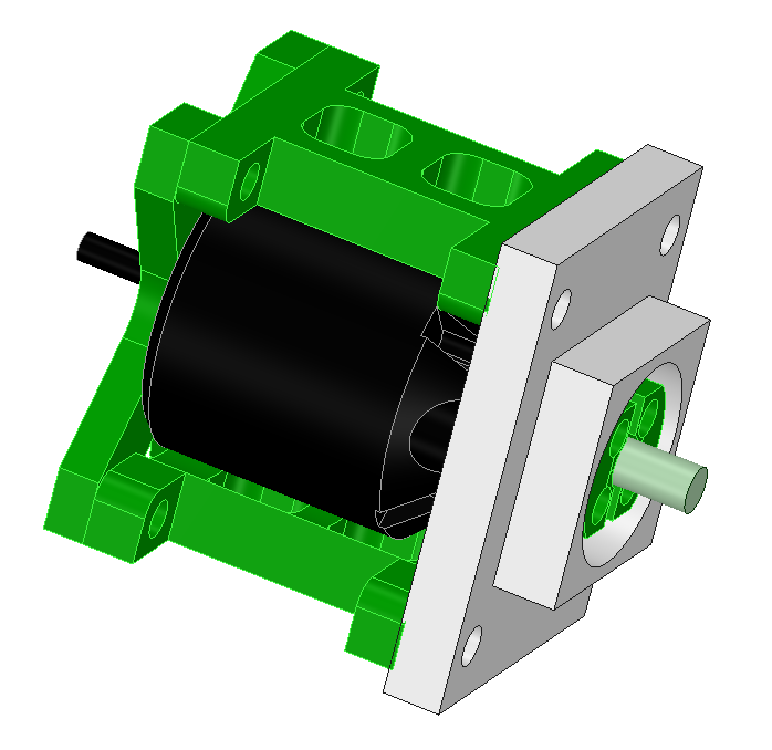
This would also help eliminate vibration as there were now two anchor points for the motor vs one with the original design.
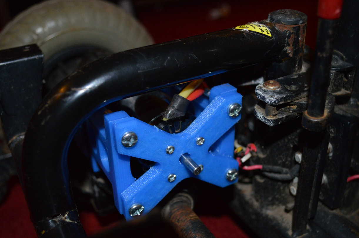
The result
The scooter actually worked quite well and did go about 15 miles per hour. With the V2 motor mount it actually was capable of pulling wheelies without damaging itself in any way. You can see in the picture below that I stuck a bike seat on it, and also rigged in a twist grip. In the picture there are 2 grey lead acid batteries which I originally tested the motor with.
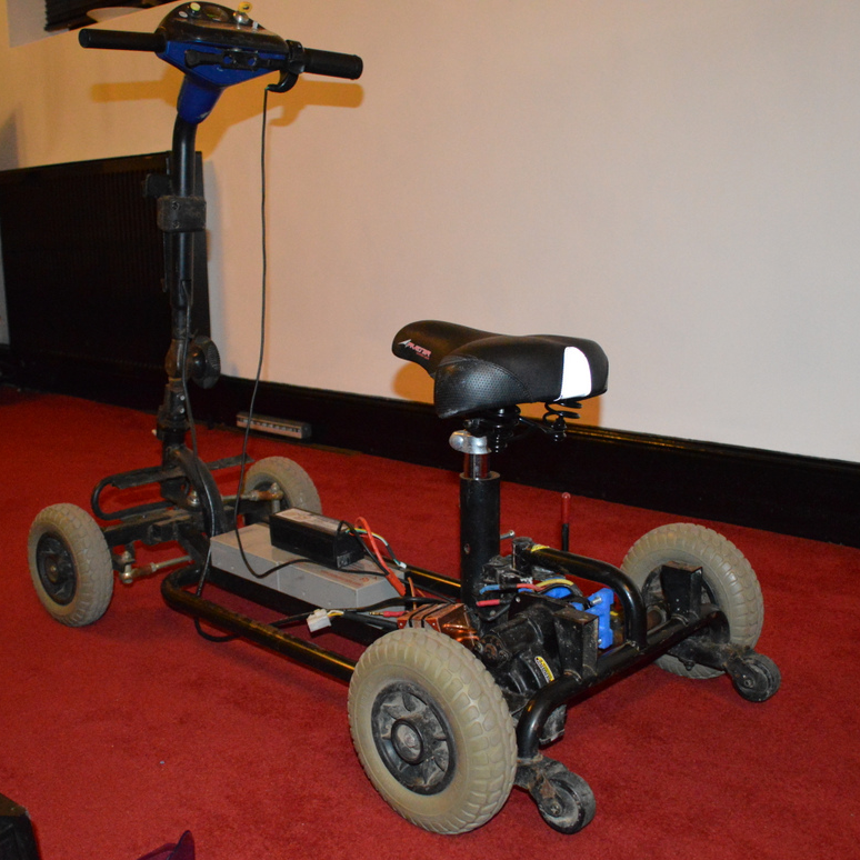
Here it is in action at night, apparently I didn’t record a video in the day time.